Description
🔗 Power your smart home like a pro—control, customize, and connect with ease!
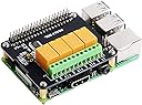
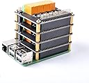
- ROBUST SCALABLE - Stack up to four layers for expanded control, future-proofing your smart home or IoT ecosystem.
- MULTI LANGUAGE SUPPORT - Develop in your preferred language with broad compatibility, perfect for professional and hobbyist coders alike.
- PLUG PLAY INSTALLATION - No programming required—get your Raspberry Pi projects up and running in minutes with easy setup.
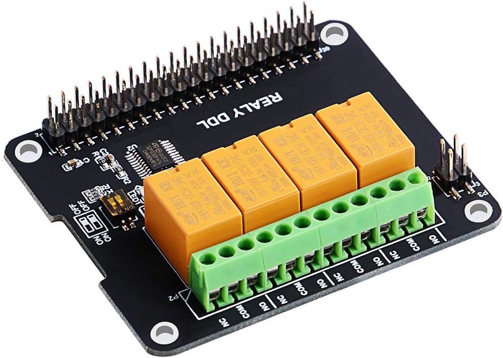
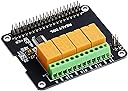
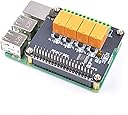
- SEAMLESS 4 RELAY CONTROL - Effortlessly manage multiple devices with four high-quality relays designed for smart home automation.
- CUSTOMIZABLE I 2 C ADDRESSING - Avoid conflicts by switching I2C addresses via DIP switches for smooth multi-module stacking.
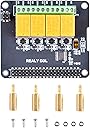
The GeeekPi 4 Channel Relay Module is a versatile expansion board compatible with Raspberry Pi 2, 3, and 4 models. Featuring four high-quality relays, it enables fast, reliable switching for smart home projects without mandatory programming. Its DIP switch-configurable I2C addresses allow stacking multiple modules without address conflicts, supporting scalable and multilingual development. Easy to install and designed for low-voltage applications, this module is ideal for professionals and makers aiming to elevate their home automation setups.